How IDE Controllers Work

By: Jeff Tyson
The Integrated Drive Electronics interface connects a hard drive to a PC.
2008 HowStuffWorks.com

No matter what you do with your computer, storage is an important part of your system. In fact, mostpersonal computershave one or more of the following storage devices:

Usually, these devices connect to the computer through anIntegrated Drive Electronics(IDE) interface. Essentially, an IDE interface is a standard way for a storage device to connect to a computer. IDE is actually not the true technical name for the interface standard. The original name,AT Attachment(ATA), signified that the interface was initially developed for the IBM AT computer. In this article, you will learn about the evolution of IDE/ATA, what the pinouts are and exactly what "slave" and "master" mean in IDE.

Advertisement

IDE Evolution

The birth of the IDE interface led to combining a controller like this one with a hard drive.

IDE was created as a way to standardize the use of hard drives in computers. The basic concept behind IDE is that the hard drive and the controller should be combined. The controller is a small circuit board with chips that provide guidance as to exactly how the hard drive stores and accesses data. Most controllers also include somememorythat acts as a buffer to enhance hard drive performance.

Before IDE, controllers and hard drives were separate and often proprietary. In other words, a controller from one manufacturer might not work with a hard drive from another manufacturer. The distance between the controller and the hard drive could result in poor signal quality and affect performance. Obviously, this caused much frustration for computer users.

Advertisement

IBM introduced the AT computer in 1984 with a couple of key innovations.

  • The slots in the computer for adding cards used a new version of theIndustry Standard Architecture(ISA) bus. The new bus was capable of transmitting information 16bitsat a time, compared to 8 bits on the original ISA bus.
  • IBM also offered a hard drive for the AT that used a new combined drive/controller. A ribbon cable from the drive/controller combination ran to an ISA card to connect to the computer, giving birth to the AT Attachment (ATA) interface.

In 1986, Compaq introduced IDE drives in their Deskpro 386. This drive/controller combination was based on the ATA standard developed by IBM. Before long, other vendors began offering IDE drives. IDE became the term that covered the entire range of integrated drive/controller devices. Since almost all IDE drives are ATA-based, the two terms are used interchangeably.

Advertisement

Controllers, Drives, Host Adapters

A close-up of the primary and secondary IDE interfaces on a motherboard

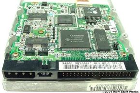
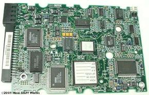
Mostmotherboardscome with an IDE interface. This interface is often referred to as an IDE controller, which is incorrect. The interface is actually ahost adapter, meaning that it provides a way to connect a complete device to the computer (host). The actual controller is on a circuit board attached to the hard drive. That's the reason it's called Integrated Drive Electronics in the first place!

While the IDE interface was originally developed for connecting hard drives, it has evolved into the universal interface for connecting internal floppy drives, CD-ROM drives and even some tape backup drives. Although it is very popular for internal drives, IDE is rarely used for attaching an external device.

Advertisement

There are several variations of ATA, each one adding to the previous standard and maintaining backward compatibility.

The standards include:

ATA-1- The original specification that Compaq included in the Deskpro 386. It instituted the use of a master/slave configuration. ATA-1 was based on a subset of the standard ISA 96-pin connector that uses either 40 or 44 pin connectors and cables. In the 44-pin version, the extra four pins are used to supply power to a drive that doesn't have a separate power connector. Additionally, ATA-1 provides signal timing fordirect memory access(DMA) and programmed input/output (PIO) functions.DMAmeans that the drive sends information directly to memory, whilePIOmeans that the computer'scentral processing unit(CPU) manages the information transfer. ATA-1 is more commonly known as IDE.

ATA-2- DMA was fully implemented beginning with the ATA-2 version. Standard DMA transfer rates increased from 4.16 megabytes per second (MBps) in ATA-1 to as many as 16.67 MBps. ATA-2 provides power management,PCMCIA cardsupport and removable device support. ATA-2 is often called EIDE (Enhanced IDE), Fast ATA or Fast ATA-2. The total hard drive size supported increased to 137.4 gigabytes. ATA-2 provided standard translation methods forCylinder Head Sector(CHS) for hard drives up to 8.4 gigabytes in size. CHS is how the system determines where the data is located on a hard drive. The reason for the big discrepancy between total hard drive size and CHS hard drive support is because of the bit sizes used by the basic input/output system (BIOS) for CHS. CHS has a fixed length for each part of the address:

  • Cylinder = 10-bit, 1024
  • Head = 8-bit, 256
  • Sector = 6-bit,63*

You will note that the number of sectors is 63 instead of 64. This is becausea sector cannot begin with zero。Each sector holds 512 bytes. If you multiply 1,024 x 256 x 63 x 512, you will get 8,455,716,864 bytes or approximately 8.4 gigabytes. Newer BIOS versions increased the bit size for CHS, providing support for the full 137.4 gigabytes.ATA-3- With the addition of Self-Monitoring Analysis and Reporting Technology (SMART), IDE drives were made more reliable. ATA-3 also adds password protection to access drives, providing a valuable security feature.

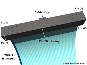
ATA-4- Probably the two biggest additions to the standard in this version are Ultra DMA support and the integration of theAT Attachment Program Interface(ATAPI) standard. ATAPI provides a common interface for CD-ROM drives, tape backup drives and otherremovable storagedevices. Before ATA-4, ATAPI was a completely separate standard. With the inclusion of ATAPI, ATA-4 immediately improved the removable media support of ATA. Ultra DMA increased the DMA transfer rate from ATA-2's 16.67 MBps to 33.33 MBps. In addition to the existing cable that uses 40 pins and 40 conductors (wires), this version introduces a cable that has 80 conductors. The other 40 conductors are ground wires interspersed between the standard 40 conductors to improve signal quality. ATA-4 is also known as Ultra DMA, Ultra ATA and Ultra ATA/33.

ATA-5- The major update in ATA-5 isauto detectionof which cable is used: the 40-conductor or 80-conductor version. Ultra DMA is increased to 66.67 MB/sec with the use of the 80-conductor cable. ATA-5 is also called Ultra ATA/66.

Advertisement

Cable Key

The connector on an IDE cable

IDE devices use aribbon cableto connect to each other. Ribbon cables have all of the wires laid flat next to each other instead of bunched or wrapped together in a bundle. IDE ribbon cables have either 40 or 80 wires. There is a connector at each end of the cable and another one about two-thirds of the distance from the motherboard connector. This cable cannot exceed 18 inches (46 cm) in total length (12 inches from first to second connector, and 6 inches from second to third) to maintain signal integrity. The three connectors are typically different colors and attach to specific items:

  • The blue connector attaches to the motherboard.
  • The black connector attaches to the primary (master) drive.
  • The grey connector attaches to the secondary (slave) drive.

Along one side of the cable is a stripe. This stripe tells you that the wire on that side is attached to Pin 1 of each connector. Wire 20 is not connected to anything. In fact, there is no pin at that position. This position is used to ensure that the cable is attached to the drive in the correct position. Another way that manufacturers make sure the cable is not reversed is by using acable key。电缆主要是一个小塑料广场之上of the connector on the ribbon cable that fits into a notch on the connector of the device. This allows the cable to attach in only one position.

Advertisement

Pin Numbers and Descriptions

  1. Reset
  2. Ground
  3. Data Bit 7
  4. Data Bit 8
  5. Data Bit 6
  6. Data Bit 9
  7. Data Bit 5
  8. Data Bit 10
  9. Data Bit 4
  10. 数据位11
  11. Data Bit 3
  12. 数据位12
  13. Data Bit 2
  14. 数据位13
  15. Data Bit 1
  16. Data Bit 14
  17. Data Bit 0
  18. Data Bit 15
  19. Ground
  20. Cable Key (pin missing)
  21. DRQ 3
  22. Ground
  23. -IOW
  24. Ground
  25. -IOR
  26. Ground
  27. I/O Channel Ready
  28. SPSYNC: Cable Select
  29. -DACK 3
  30. Ground
  31. RQ 14
  32. 国际石油公司16
  33. Address Bit 1
  34. -PDIAG
  35. Address Bit 0
  36. Address Bit 2
  37. -CS1FX
  38. -CS3FX
  39. -DA/SP
  40. Ground
  41. +5 Volts (Logic) (Optional)
  42. +5 Volts (Motor) (Optional)
  43. Ground (Optional)
  44. -Type (Optional)

Note that the last four pins are only used by devices that require power through the ribbon cable. Typically, such devices are hard drives that are too small (for example, 2.5 inches) to need a separate power supply.

Advertisement

Masters and Slaves

A single IDE interface can support two devices. Most motherboards come withdual IDE interfaces(primary and secondary) for up to four IDE devices. Because the controller is integrated with the drive, there is no overall controller to decide which device is currently communicating with the computer. This is not a problem as long as each device is on a separate interface, but adding support for a second drive on the same cable took some ingenuity.

To allow for two drives on the same cable, IDE uses a special configuration calledmasterandslave。This configuration allows one drive's controller to tell the other drive when it can transfer data to or from the computer. What happens is the slave drive makes a request to the master drive, which checks to see if it is currently communicating with the computer. If the master drive is idle, it tells the slave drive to go ahead. If the master drive is communicating with the computer, it tells the slave drive to wait and then informs it when it can go ahead.

Advertisement

The computer determines if there is a second (slave) drive attached through the use of Pin 39 on the connector. Pin 39 carries a special signal, calledDrive Active/Slave Present(DASP), checks to see if a slave drive is present.

Although it will work in either position, it is recommended that the master drive is attached to the connector at the very end of the IDE ribbon cable. Then, a jumper on the back of the drive next to the IDE connector must be set in the correct position to identify the drive as the master drive. The slave drive must have either the master jumper removed or a special slave jumper set, depending on the drive. Also, the slave drive is attached to the connector near the middle of the IDE ribbon cable. Each drive's controller board looks at the jumper setting to determine whether it is a slave or a master. This tells them how to perform. Every drive is capable of being either slave or master when you receive it from the manufacturer. If only one drive is installed, it should always be the master drive.

Many drives feature an option calledCable Select(CS). With the correct type of IDE ribbon cable, these drives can be auto configured as master or slave. CS works like this: A jumper on each drive is set to the CS option. The cable itself is just like a normal IDE cable except for one difference -- Pin 28 only connects to the master drive connector. When your computer is powered up, the IDE interface sends a signal along the wire for Pin 28. Only the drive attached to the master connector receives the signal. That drive then configures itself as the master drive. Since the other drive received no signal, it defaults to slave mode.

For more information, check out the links on the next page.

Advertisement

Frequently Answered Questions

How many IDE controllers can a PC motherboard support?
Most PC motherboards support two IDE controllers.
What is the IDE controller?
The IDE controller is a device that is used to connect IDE devices to a computer system. IDE devices include hard drives, optical drives, and floppy drives. The IDE controller allows these devices to be connected to the computer system via a single interface.

Advertisement

Loading...